

| Appearance | Sensing distance | Model | ||
|---|---|---|---|---|
| NO | NC | |||
 *1 |
M12 | 4 mm | E2EM-X4X1 2M *2 | E2EM-X4X2 2M |
| M18 | 8 mm | E2EM-X8X1 2M *2 | E2EM-X8X2 2M | |
| M30 | 15 mm | E2EM-X15X1 2M *2 | E2EM-X15X2 2M | |
 |
M18 | 16 mm | E2EM-X16MX1 2M | E2EM-X16MX2 2M |
| M30 | 30 mm | E2EM-X30MX1 2M | E2EM-X30MX2 2M | |

Liên hệ

• Khả năng phát hiện khoảng cách dài lên đến 30 mm cho phép lắp đặt an toàn và giảm các sự cố do va chạm phôi.
• Không có cực tính để dễ dàng đấu dây với kiểu máy 2 dây DC.
• Bộ bảo vệ cáp được cung cấp như một tính năng tiêu chuẩn.
| Appearance | Sensing distance | Model | ||
|---|---|---|---|---|
| NO | NC | |||
|
*1 |
M12 | 4 mm | E2EM-X4X1 2M *2 | E2EM-X4X2 2M |
| M18 | 8 mm | E2EM-X8X1 2M *2 | E2EM-X8X2 2M | |
| M30 | 15 mm | E2EM-X15X1 2M *2 | E2EM-X15X2 2M | |
|
|
M18 | 16 mm | E2EM-X16MX1 2M | E2EM-X16MX2 2M |
| M30 | 30 mm | E2EM-X30MX1 2M | E2EM-X30MX2 2M | |
| Appearance | Sensing distance | Model | ||
|---|---|---|---|---|
| Output configuration: NPN NO | Output configuration: NPN NC | |||
|
* |
M8 | 2 mm | E2EM-X2C1 2M | E2EM-X2C2 2M |
| M12 | 4 mm | E2EM-X4C1 2M | E2EM-X4C2 2M | |
| M18 | 8 mm | E2EM-X8C1 2M | E2EM-X8C2 2M | |
| M30 | 15 mm | E2EM-X15C1 2M | E2EM-X15C2 2M | |
| Appearance | Sensing distance | Model | ||
|---|---|---|---|---|
| Output configuration: NPN NO | Output configuration: NPN NC | |||
 * |
M8 | 2 mm | E2EM-X2C1-M1 | E2EM-X2C2-M1 |
| M12 | 4 mm | E2EM-X4C1-M1 | E2EM-X4C2-M1 | |
| M18 | 8 mm | E2EM-X8C1-M1 | E2EM-X8C2-M1 | |
| M30 | 15 mm | E2EM-X15C1-M1 | E2EM-X15C2-M1 | |
(Models for Connectors and with Pre-wired Connectors: A Connector is not provided with the Sensor. Be sure to order a Connector separately.)
| Appearance | Cable length | Sensor I/O Connector model number | Applicable Proximity Sensor model number |
|---|---|---|---|
 |
2 m | XS2F-D421-DC0-F | E2EM-X[]C1-M1 |
| 5 m | XS2F-D421-GC0-F | ||
| 2 m | XS2F-D421-D80-F | E2EM-X[]C[]-M1 | |
| 5 m | XS2F-D421-G80-F | ||
 |
2 m | XS2F-D422-DC0-F | E2EM-X[]C1-M1 |
| 5 m | XS2F-D422-GC0-F | ||
| 2 m | XS2F-D422-D80-F | E2EM-X[]C[]-M1 | |
| 5 m | XS2F-D422-G80-F |
| Size | M12 | M18 | M30 | |||
|---|---|---|---|---|---|---|
| Shielded | Shielded | Shielded | Unshielded | Shielded | Unshielded | |
| Model | E2EM-X4X[] | E2EM-X8X[] | E2EM-X16MX[] | E2EM-X15X[] | E2EM-X30MX[] | |
| ensing distance | 4 mm ±10% | 8 mm ±10% | 16 mm ±10% | 15 mm ±10% | 30 mm ±10% | |
| Set distance *1 | 0 to 3.2 mm | 0 to 6.4 mm | 0 to 12.8 mm | 0 to 12 mm | 0 to 24 mm | |
| Differential travel | 15% max. of sensing distance | |||||
| Detectable object | Ferrous metal (The sensing distance decreases with non-ferrous metal. Refer to Engineering Data on Data Sheet.) |
|||||
| Standard sensing object | Iron, 12 × 12 × 1 mm | Iron, 18 × 18 × 1 mm | Iron, 45 × 45 × 1 mm | Iron, 30 × 30 × 1 mm | Iron, 70 × 70 × 1 mm | |
| Response frequency *2 | 1 kHz | 0.5 kHz | 0.4 kHz | 0.25 kHz | 0.1 kHz | |
| Power supply voltage (operating voltage range) |
12 to 24 VDC (10 to 30 VDC), ripple (p-p): 10% max. | |||||
| Leakage current | 0.8 mA max. | |||||
| Control output |
Load current |
3 to 100 mA | ||||
| Residual voltage *3 |
5 V max. (Load current: 100 mA, Cable length: 2 m) | |||||
| Indicators | X1 Models: Operation indicator (red), Setting indicator (green) X2 Models: Operation indicator (red) |
|||||
| Operation mode (with sensing object approaching) |
X1 Models: NO X2 Models: NC Refer to the timing charts under I/O Circuit Diagrams on Data Sheet for details. |
|||||
| Protection circuits | Surge suppressor, Load short-circuit protection | |||||
| Ambient temperature range | Operating: -25 to 70°C, Storage: -40 to 85°C (with no icing or condensation) | |||||
| Ambient humidity range | Operating/Storage: 35% to 95% (with no condensation) | |||||
| Temperature influence | ±15% max. of sensing distance at 23°C in the temperature range of -25 to 70°C | |||||
| Voltage influence | ±1% max. of sensing distance at rated voltage in the rated voltage ±15% range | |||||
| Insulation resistance | 50 MΩ min. (at 500 VDC) between current-carrying parts and case | |||||
| Dielectric strength | 1,000 VAC, 50/60 Hz for 1 minute between current-carrying parts and case | |||||
| Vibration resistance | Destruction: 10 to 55 Hz, 1.5-mm double amplitude for 2 hours each in X, Y, and Z directions | |||||
| Shock resistance | Destruction: 1,000 m/s2 10 times each in X, Y, and Z directions | |||||
| Degree of protection | IEC 60529 IP67, in-house standards: oil-resistant | |||||
| Connection method | Pre-wired Models (Standard cable length: 2 m) | |||||
| Weight (packed state) | Approx. 60 g | Approx. 130 g | Approx. 150 g | Approx. 180 g | Approx. 210 g | |
| Materials | Case | Nickel-plated brass | ||||
| Sensing surface |
PBT | |||||
| Clamping nuts |
Nickel-plated brass | |||||
| Toothed washer |
Zinc-plated iron | |||||
| Accessories | Instruction manual | |||||
| Size | M8 | M12 | M18 | M30 | |
|---|---|---|---|---|---|
| Shielded | Shielded | Shielded | Shielded | Shielded | |
| Model | E2EM-X2C[](-M1) | E2EM-X4C[](-M1) | E2EM-X8C[](-M1) | E2EM-X15C[](-M1) | |
| Sensing distance | 2 mm ±10% | 4 mm ±10% | 8 mm ±10% | 15 mm ±10% | |
| Set distance | 0 to 1.6 mm | 0 to 3.2 mm | 0 to 6.4 mm | 0 to 12 mm | |
| Differential travel | 10% max. of sensing distance | ||||
| Detectable object | Ferrous metal (The sensing distance decreases with non-ferrous metal. Refer to Engineering Data on Data Sheet.) |
||||
| Standard sensing object | Iron, 8 × 8 × 1 mm | Iron, 12 × 12 × 1 mm |
Iron, 18 × 18 × 1 mm |
Iron, 30 × 30 × 1 mm |
|
| Response frequency *1 | 1.5 kHz | 0.5 kHz | 0.3 kHz | 0.1 kHz | |
| Power supply voltage (operating voltage range) *2 |
12 to 24 VDC (10 to 30 VDC), ripple (p-p): 10% max. | ||||
| Current consumption | 13 mA max. | ||||
| Control output |
Load current *2 |
200 mA max. | |||
| Residual voltage |
2 V max. (Load current: 200 mA, Cable length: 2 m) | ||||
| Indicators | Operation indicator (yellow) | ||||
| Operation mode (with sensing object approaching) |
C1 Models: NO C2 Models: NC Refer to the timing charts under I/O Circuit Diagrams on Data Sheet for details. |
||||
| Protection circuits | Reverse polarity protection, Load short-circuit protection, Surge suppressor | ||||
| Ambient temperature range *1 |
Operating/Storage: -40 to 85°C (with no icing or condensation) | Operating: -25 to 70°C Storage: -40 to 85°C (with no icing or condensation) |
|||
| Ambient humidity range | Operating/Storage: 35% to 95% (with no condensation) | ||||
| Temperature influence | ±15% max. of sensing distance at 23°C in the temperature range of -40 to 85°C ±10% max. of sensing distance at 23°C in the temperature range of -25 to 70°C |
±15% max. of sensing distance at 23°C in the temperature range of -25 to 70°C |
|||
| Voltage influence | ±1% max. of sensing distance at rated voltage in the rated voltage ±15% range | ||||
| Insulation resistance | 50 MΩ min. (at 500 VDC) between current-carrying parts and case | ||||
| Dielectric strength | 1,000 VAC, 50/60 Hz for 1 minute between current-carrying parts and case | ||||
| Vibration resistance | Destruction: 10 to 55 Hz, 1.5-mm double amplitude for 2 hours each in X, Y, and Z directions |
||||
| Shock resistance | Destruction: 500 m/s2 10 times each in X, Y, and Z directions |
Destruction: 1,000 m/s2 10 times each in X, Y, and Z directions | |||
| Degree of protection | Pre-wired Models: IEC 60529 IP67, in-house standards: oil-resistant Connector Models: IEC 60529 IP67 |
||||
| Connection method | Pre-wired Models (Standard cable length: 2 m) Connector Models |
||||
| Weight (packed state) |
Pre-wired Models |
Approx. 65 g | Approx. 75 g | Approx. 150 g | Approx. 195 g |
| Connector Models |
Approx. 15 g | Approx. 25 g | Approx. 40 g | Approx. 90 g | |
| Materials | Case | Stainless steel (SUS303) |
Nickel-plated brass | ||
| Sensing surface |
PBT | ||||
| Clamping nuts |
Nickel-plated brass | ||||
| Toothed washer |
Zinc-plated iron | ||||
| Accessories | Instruction manual | ||||
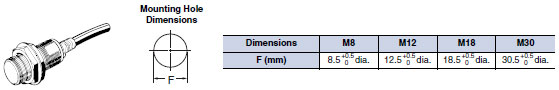
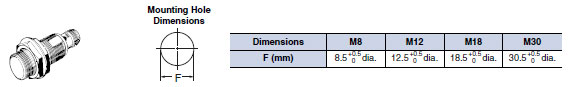
Note:Tolerance class IT16 applies to dimensions in this data sheet unless otherwise specified.
![E2EM Dimensions 4 E2EM-X2C[]_Dim](https://www.omron.com.vn/Images/E2EM_dm_227-112819.jpg)
![E2EM Dimensions 5 E2EM-X4[][]_Dim](https://www.omron.com.vn/Images/E2EM_dm_327-112821.jpg)
![E2EM Dimensions 7 E2EM-X8[][]_Dim](https://www.omron.com.vn/Images/E2EM_dm_427-112824.jpg)
![E2EM Dimensions 8 E2EM-X15[][]_Dim](https://www.omron.com.vn/Images/E2EM_dm_527-112826.jpg)

![E2EM Dimensions 12 E2EM-X16MX[]_Dim](https://www.omron.com.vn/Images/E2EM_dm_727-112830.jpg)
![E2EM Dimensions 14 E2EM-X30MX[]_Dim](https://www.omron.com.vn/Images/E2EM_dm_827-112832.jpg)
![E2EM Dimensions 17 E2EM-X2C[]-M1_Dim](https://www.omron.com.vn/Images/E2EM_dm_1027-112836.jpg)
![E2EM Dimensions 18 E2EM-X4C[]-M1_Dim](https://www.omron.com.vn/Images/E2EM_dm_1127-112838.jpg)
![E2EM Dimensions 19 E2EM-X8C[]-M1_Dim](https://www.omron.com.vn/Images/E2EM_dm_1227-112840.jpg)
![E2EM Dimensions 20 E2EM-X15C[]-M1_Dim](https://www.omron.com.vn/Images/E2EM_dm_1327-112842.jpg)


Reviews
There are no reviews yet.