
| Appearance | Beam Gap between Muting Trigger Beams |
output | Number of Beams | Model |
|---|---|---|---|---|
 |
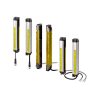
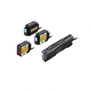
100 mm | PNP output | 8 | F3W-MA0100P |
| 300 mm | 20 | F3W-MA0300P |

Liên hệ

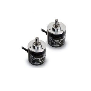
• Hệ thống ngắt tiếng có thể được cấu hình dễ dàng kết hợp với màn chắn sáng an toàn.
• Chức năng ngắt có thể được thực hiện ổn định ngay cả khi phôi có lỗ đi qua.
| Appearance | Beam Gap between Muting Trigger Beams |
output | Number of Beams | Model |
|---|---|---|---|---|
|
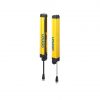
100 mm | PNP output | 8 | F3W-MA0100P |
| 300 mm | 20 | F3W-MA0300P |
Note: Use with the PNP output model safety light curtain.
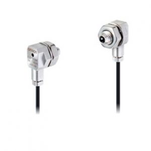
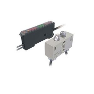
| Appearance | Type | Cable length |
Specifications | Model |
|---|---|---|---|---|
 |
M12 connector (5-pin), 5 wires Color: Gray |
3 m |  |
F39-JG3A-L |
| 7 m | F39-JG7A-L | |||
| 10 m | F39-JG10A-L | |||
| 15 m | F39-JG15A-L | |||
| 20 m | F39-JG20A-L | |||
| For receiver M12 connector (8-pin), 8 wires Color: Black |
3 m |  |
F39-JG3A-D | |
| 7 m | F39-JG7A-D | |||
| 10 m | F39-JG10A-D | |||
| 15 m | F39-JG15A-D | |||
| 20 m | F39-JG20A-D |
* A set of two Single-Ended Cables (one for emitter and one for receiver) is also available.
Model: Model number without the -L/-D at the end (F39-JG[]A)
| Appearance | Type | Cable length |
Specifications | Model |
|---|---|---|---|---|
 |
M12 connector (5-pin) on both ends Color: Gray |
0.5 m |  |
F39-JGR5B-L |
| 1 m | F39-JG1B-L | |||
| 3 m | F39-JG3B-L | |||
| 5 m | F39-JG5B-L | |||
| 7 m | F39-JG7B-L | |||
| 10 m | F39-JG10B-L | |||
| 15 m | F39-JG15B-L | |||
| 20 m | F39-JG20B-L | |||
| M12 connector (8-pin) on both ends Color: Black |
0.5 m |  |
F39-JGR5B-D | |
| 1 m | F39-JG1B-D | |||
| 3 m | F39-JG3B-D | |||
| 5 m | F39-JG5B-D | |||
| 7 m | F39-JG7B-D | |||
| 10 m | F39-JG10B-D | |||
| 15 m | F39-JG15B-D | |||
| 20 m | F39-JG20B-D |
* A set of two Double-Ended Cables (one for emitter and one for receiver) is also available.
Model: Model number without the -L/-D at the end (F39-JG[]B)
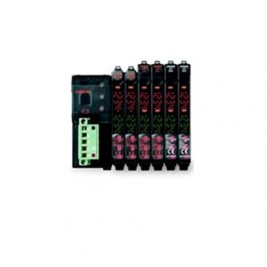
| Appearance | Type | Specifications | Model |
|---|---|---|---|
 |
For emitter M12 connectors. Used for reduced wiring. |
 |
F39-GCN4-L |
 |
For receiver (PNP output) M12 connectors. Used for reduced wiring. |
 |
F39-GCN4-D |
 |
Includes one each of F39-GCN4-L and F39-GCN4-D |
– | F39-GCN4 |
 |
Water-resistive Cover for 4-Joint Plug/Socket Connector |
One water-resistive cover for an F39-GCN4-L/-D 4-Joint Plug/Socket Connector. You can use this when the MA2 connector part is not used. Material: PBT. IP67 rated when attached. Smartclick mechanism. |
XS5Z-11 |
 |
Dust Cover for 4-Joint Plug/Socket Connector |
One dust cover for an F39-GCN4-L/-D 4-Joint Plug/ Socket Connector. You can use this when the MA2 connector part is not used. Material: Rubber/black. This cover does not ensure IP67 degree of protection. XS2Z-14: Attach to a pin block inside the M12 female screw. XS2Z-15: Attach to a M12 female screw. When attaching the cover to the connector, press the cover onto the connector until the connector is fully inserted into the cover. |
XS2Z-14 |
 |
XS2Z-15 |
| Appearance | Specification | Application | Remarks | Model |
|---|---|---|---|---|
 |
Standard Fixed Bracket |
Bracket to mount the F3W-MA. Side mounting and backside mounting possible. |
Two brackets per set |
F39-LGF |
 |
Standard Adjustable Bracket |
Bracket to mount the F3W-MA. Beam alignment after mounting possible.The angle adjustment range is ±15°. Side mounting and backside mounting possible. |
Two brackets per set |
F39-LGA |
 |
F3W-MA Bracket |
Bracket to fix the F3W-MA to the F3SG-RA. F39-LGMAL: L-shaped configuration F39-LGMAT: T-shaped configuration Beam alignment after mounting possible. When using the F3W-MA Bracket, it is necessary to add an extra Standard Adjustable Bracket (F39-LGA) to the F3SG-RA. * Please also purchase Standard Adjustable Bracket (F39-LGA). |
Two brackets per set |
F39-LGMAL |
 |
F39-LGMAT |
| F3W-MA0100P | F3W-MA0300P | |||
|---|---|---|---|---|
| Perfor- mance |
Beam Gap between Muting Trigger Beams |
100 mm | 300 mm | |
| Number of Beams | 8 | 20 | ||
| Standard Detection Object | 30 mm | |||
| Operating Range |
Long | 0.3 to 20.0 m (1 to 65 ft.) | ||
| Short | 0.3 to 7.0 m (1 to 23 ft.) | |||
| Response Time |
Operation | 13 ms max. | ||
| Reset | 26 ms max. (Synchronized) 78 ms max. (Not synchronized) |
|||
| Effective Aperture Angle | ±2.5° max., emitter and receiver at operating range of 3 m or greater | |||
| Light Source | Infrared LEDs, Wavelength: 870 nm | |||
| Startup Waiting Time | 2 s max. | |||
| Elec- trical |
Power Supply Voltage (Vs) | SELV/PELV 24 VDC±20% (ripple p-p 10% max.) | ||
| Current Consumption |
Emitter | 35 mA | 45 mA | |
| Receiver | 75 mA | 75 mA | ||
| Muting Outputs | Two PNP transistor outputs. * Load current of 300 mA max., Residual voltage of 2 V max. (except for voltage drop due to cable extension) |
|||
| * This product is a PNP output model. Use with the PNP output model safety light curtain. | ||||
| Output Operation Mode |
Muting Output A |
Dark-ON (Muting Output A is enabled when MUTE A trigger beam is blocked.) |
||
| Muting Output B |
Dark-ON (Muting Output B is enabled when MUTE B trigger beam is blocked.) |
|||
| Input Voltage |
ON Voltage | [MUTE Enable] Vs to Vs-3 V (sink current 5 mA max.) * | ||
| OFF Voltage | [MUTE Enable] 0 to 1/2 Vs, or open * | |||
| * The Vs indicates a supply voltage value in your environment. | ||||
| Indicators | Refer to “LED Indicator Status”. | |||
| Protective Circuit | Protective Circuit Output short protection, Power supply reverse polarity protection | |||
| Insulation Resistance | 20 MΩ or higher (500 VDC megger) | |||
| Dielectric Strength | 1,000 VAC, 50/60 Hz (1 min) | |||
| Func- tional |
Functions | – Scan Code Selection – Operation Mode Selection (Point to Point Detection/Chattering and Void Space Prevention) – Off-Delay – Muting Enable – Muting Trigger Beam Allocation – Operating Range Selection |
||
| Environ- mental |
Ambient Temperature |
Operating | -10 to 55°C (13 to 131°F) (non-icing) | |
| Storage | -25 to 70°C (-13 to 158°F) | |||
| Ambient Humidity |
Operating | 35% to 85% (non-condensing) | ||
| Storage | 35% to 95% | |||
| Ambient Illuminance | Incandescent lamp: 3,000 Ix max. on receiver surface Sunlight: 10,000 Ix max. on receiver surface |
|||
| Degree of Protection (IEC 60529) |
IP65 and IP67 | |||
| Vibration Resistance (IEC 61496-1) |
10 to 55 Hz, Multiple amplitude of 0.7 mm, 20 sweeps for all 3 axes | |||
| Shock Resistance (IEC 61496-1) |
100 m/s2, 1000 shocks for all 3 axes | |||
| Pollution Degree (IEC 60664-1) |
Pollution Degree 3 | |||
| Connec- tions |
Power Cable | Type of Connection |
M12 connectors: 5-pin emitter, 8-pin receiver, IP67 rated when mated, Cables prewired to sensors | |
| Number of Wires |
Emitter: 5, Receiver: 8 | |||
| Cable Length |
0.3 mm | |||
| Cable Diameter |
6 mm | |||
| Minimum Bending Radius |
R5 mm | |||
| Extension of Power Cable | 100 m max. Note: For T-Shaped configuration with COM lines, the length of cable extension is 30 m max. |
|||
| Material | Housing: Aluminum alloy, Cap: PBT resin, Front window: Acrylic resin, Cable: Oil-resistant PVC resin, FE plate: Stainless steel | |||
| Net Weight *1 | 0.7 kg | 0.9 kg | ||
| Gross Weight *2 | 1.3 kg | 2.2 kg | ||
| Included Accessories | Instruction Sheet | |||
*1. The net weight is the weight of an emitter and a receiver.
*2. The gross weight is the weight of an emitter, a receiver, included accessories and a package.
Shown below are indication statuses of F3W-MA LED indicators when you purchased.
| Name of Indicator | Color | Illuminated | Blinking | |
|---|---|---|---|---|
| Operating range | LONG | Green | Long Range mode is selected by DIP Switch. |
– |
| Running | RUN | Green | Power is ON. | – |
| Error | ERR | Red | – | Error in emitter. Generic error happens. |
| Name of Indicator | Color | Illuminated | Blinking | |
|---|---|---|---|---|
| Top-beam-state | TOP | Blue | The top beam is unblocked. | – |
| Muting output A | MUTE A | Green | Muting Output A is activated. | – |
| Muting output B | MUTE B | Green | Muting Output B is activated. | – |
| Off-Delay | DELAY | Yellow | Off-Delay function is enabled by DIP Switch. |
– |
| Chattering/ Void space |
CHAT | Green | Chattering and Void Space Prevention mode is selected by DIP Switch. |
– |
| Muting Enable | MUTE DISABLE |
Red | The Muting Enable function is enabled and Muting Enable input is turned OFF by DIP Switch. |
– |
| Error | ERR | Red | – | Error in receiver. Generic error happens. |
| Stable-state | STB | Green | Incident light level is 170% or higher of ON-threshold |
– |
| Running | RUN | Green | Power is ON. | – |
| Communication | COM | Green | Synchronization between emitter and receiver is maintained. |
Primary sensor]
– Start-up (for approx. 3 s) – Synchronization between emitter and receiver is lost |
| Bottom-beamstate | BTM | Blue | The bottom beam is unblocked. | – |
(Unit: mm)
| STT | Chi tiết | Tiêu đề | Tải xuống |
| 1 | DANH SÁCH MODEL | F3W-MA | Item list of F3W-MA |
| STT | Chi tiết | Tiêu đề | Tải xuống |
| 1 | TÀI LIỆU | F3W-MA |


Reviews
There are no reviews yet.