
| Size | Sensing distance | Output | Operation mode | Model | |
|---|---|---|---|---|---|
Shielded
 |
M8 | 1.5 mm | DC 2-Wire (polarity) | NO | E2FM-X1R5D1 2M * |
| M12 | 2 mm | E2FM-X2D1 2M * | |||
| M18 | 5 mm | E2FM-X5D1 2M * | |||
| M30 | 10 mm | E2FM-X10D1 2M * | |||

Liên hệ

• Khả năng chống bắn tóe vượt trội.
• Đã thêm các Mô hình Khoảng cách Cảm biến Dài cho khoảng cách cảm biến lên tới 15 mm.
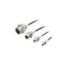
• Các mẫu Smartclick Connector có dây sẵn cũng có sẵn.
| Size | Sensing distance | Output | Operation mode | Model | |
|---|---|---|---|---|---|
| Shielded
|
M8 | 1.5 mm | DC 2-Wire (polarity) | NO | E2FM-X1R5D1 2M * |
| M12 | 2 mm | E2FM-X2D1 2M * | |||
| M18 | 5 mm | E2FM-X5D1 2M * | |||
| M30 | 10 mm | E2FM-X10D1 2M * | |||
| Size | Sensing distance | Output | Operation mode | Model | |
|---|---|---|---|---|---|
Shielded
 |
M8 | 1.5 mm | Polarity Pin allocations: 1-4 | NO | E2FM-X1R5D1-M1TGJ 0.3M |
| M12 | 2 mm | Polarity Pin allocations: 1-4 | E2FM-X2D1-M1TGJ 0.3M | ||
| No polarity Pin allocations: 3-4 | E2FM-X2D1-M1TGJ-T 0.3M | ||||
| M18 | 5 mm | Polarity Pin allocations: 1-4 | E2FM-X5D1-M1TGJ 0.3M | ||
| No polarity Pin allocations: 3-4 | E2FM-X5D1-M1TGJ-T 0.3M | ||||
| M30 | 10 mm | Polarity Pin allocations: 1-4 | E2FM-X10D1-M1TGJ 0.3M | ||
| No polarity Pin allocations: 3-4 | E2FM-X10D1-M1TGJ-T 0.3M | ||||
| Size | Sensing distance | Model | ||
|---|---|---|---|---|
| Output configuration: NPN NO | Output configuration: PNP NO | |||
| Shielded
|
M8 | 1.5 mm | E2FM-X1R5C1 2M | E2FM-X1R5B1 2M |
| M12 | 2 mm | E2FM-X2C1 2M | E2FM-X2B1 2M | |
| M18 | 5 mm | E2FM-X5C1 2M | E2FM-X5B1 2M | |
| M30 | 10 mm | E2FM-X10C1 2M | E2FM-X10B1 2M | |
Note: Models with NC operation are also available. Ask your OMRON representative for details.
| Size | Sensing distance | Model | ||
|---|---|---|---|---|
| Output configuration: NPN NO | Output configuration: PNP NO | |||
Shielded
 |
M8 | 1.5 mm | E2FM-X1R5C1-M1 | E2FM-X1R5B1-M1 * |
| M12 | 2 mm | E2FM-X2C1-M1 | E2FM-X2B1-M1 * | |
| M18 | 5 mm | E2FM-X5C1-M1 | E2FM-X5B1-M1 * | |
| M30 | 10 mm | E2FM-X10C1-M1 | E2FM-X10B1-M1 * | |
(Models for Connectors and with Pre-wired Connectors: A Connector is not provided with the Sensor. Be sure to order a Connector separately.)
| Appearance | Cable length |
Sensor I/O Connector model number |
Applicable Proximity Sensor model number |
|---|---|---|---|
Straight
 |
2 m | XS2F-D421-DC0-F | E2FM-X[]C1-M1 E2FM-X[]B1-M1 |
| 5 m | XS2F-D421-GC0-F | ||
L-shape
 |
2 m | XS2F-D422-DC0-F | |
| 5 m | XS2F-D422-GC0-F | ||
Smartclick Connector Relay Models (M12)
 |
2 m | XS5F-D421-D80-F | E2FM-X[]D1-M1TGJ E2FM-X[]D1-M1TGJ-T |
| 5 m | XS5F-D421-G80-F |
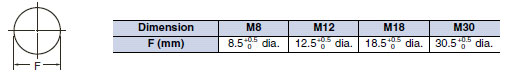
| Size | M8 | M12 | M18 | M30 | M12 | M18 | M30 | |
|---|---|---|---|---|---|---|---|---|
| Shielded | Shielded | |||||||
| Model | E2FM- X1R5D1-[] |
E2FM- X2D1-[] |
E2FM- X5D1-[] |
E2FM- X10D1[] |
E2FM- X2D1- M1T1GJ-T |
E2FM- X5D1- M1T1GJ-T |
E2FM- X10D1- M1T1GJ-T |
|
| Sensing distance | 1.5 mm±10% | 2 mm ±10% |
5 mm ±10% |
10 mm ±10% |
2 mm±10% | 5 mm±10% | 10 mm±10% | |
| Set distance | 0 to 1.05 mm | 0 to 1.4 mm |
0 to 3.5 mm |
0 to 7 mm |
0 to 1.4 mm | 0 to 3.5 mm | 0 to 7 mm | |
| Differential travel | 15% max. of sensing distance | |||||||
| Sensing object | Ferrous metal (The sensing distance decreases with non-ferrous metal. Refer to Engineering Data on Catalog.) |
|||||||
| Standard sensing object | Iron, 8 × 8 × 1 mm |
Iron, 12 × 12 × 1 mm |
Iron, 30 × 30 × 1 mm |
Iron, 54 × 54 × 1 mm |
Iron, 12 × 12 × 1 mm |
Iron, 30 × 30 × 1 mm |
Iron, 54 × 54 × 1 mm |
|
| Response frequency *1 |
200 Hz | 100 Hz | 100 Hz | 50 Hz | 100 Hz | 100 Hz | 50 Hz | |
| Power supply voltage (operating voltage range) |
12 to 24 VDC (10 to 30 VDC), ripple (p-p): 10% max. | |||||||
| Leakage current | 0.8 mA max. | |||||||
| Output configuration | With polarity | No polarity | ||||||
| Control output |
Switching capacity |
3 to 100 mA | ||||||
| Residual voltage |
3 V max. (Load current: 100 mA max., Cable length: 2 m) |
5 V max. (Load current: 100 mA max., Cable length: 2 m) |
||||||
| Indicators | Operation indicator (red LED), Setting/Operation indicator (green LED) | |||||||
| Operation mode (with sensing object approaching) |
NO *2 | |||||||
| Protection circuits | Surge suppressor, Load short-circuit protection | |||||||
| Ambient temperature range |
Operating/Storage: -25 to 70°C (with no icing or condensation) | |||||||
| Ambient humidity range |
Operating/Storage: 35% to 95% (with no condensation) | |||||||
| Temperature influence | ±20% max. of sensing distance at 23°C in the temperature range of -25 to 70°C. | |||||||
| Voltage influence | ±1% max. of sensing distance at rated voltage in the rated voltage ±15% range | |||||||
| Insulation resistance | 50 MΩ min. (at 500 VDC) between current-carrying parts and case | |||||||
| Dielectric strength | 1,000 VAC, 50/60 Hz for 1 minute between current-carrying parts and case | |||||||
| Vibration resistance | Destruction: 10 to 55 Hz, 1.5-mm double amplitude for 2 hours each in X, Y, and Z directions | |||||||
| Shock resistance | Destruction: 500 m/s2 10 times each in X, Y, and Z directions |
Destruction: 1,000 m/s2 10 times each in X, Y, and Z directions | ||||||
| Degree of protection | IEC 60529 IP67 | |||||||
| Connection method | Unmarked: Pre-wired Models (Standard cable length: 2 m) Models ending with -M1GJ-[]: Pre-wired Connector Models (Standard cable length: 300 mm) |
|||||||
| Weight (packed state) |
Pre-wired Models (2 m) |
Approx. 105 g | Approx. 190 g |
Approx. 215 g |
Approx. 295 g |
— | — | — |
| Pre-wired Connector Models |
Approx. 65 g | Approx. 85 g |
Approx. 110 g |
Approx. 190 g |
Approx. 85 g | Approx. 110 g | Approx. 190 g | |
| Mate- rials |
Case | Stainless steel (SUS303) | ||||||
| Sensing surface (thickness) |
Stainless steel (SUS303) | |||||||
| (0.4 mm) | (0.8 mm) | (0.8 mm) | ||||||
| Clamping nuts |
Stainless steel (SUS303) | |||||||
| Cable | PVC (flame retardant) | |||||||
| Toothed washer |
Zinc-plated iron | |||||||
| Accessories | Instruction manual | |||||||
| Size | M8 | M12 | M18 | M30 | |
|---|---|---|---|---|---|
| Shielded | Shielded | ||||
| Model | E2FM-X1R5[] | E2FM-X2[] | E2FM-X5[] | E2FM-X10[] | |
| Sensing distance | 1.5 mm±10% | 2 mm±10% | 5 mm±10% | 10 mm±10% | |
| Set distance | 0 to 1.05 mm | 0 to 1.4 mm | 0 to 3.5 mm | 0 to 7 mm | |
| Differential travel | 15% max. of sensing distance | ||||
| Sensing object | Ferrous metal (The sensing distance decreases with non-ferrous metal. Refer to Catalog.) | ||||
| Standard sensing object |
Iron, 8 × 8 × 1 mm | Iron, 12 × 12 × 1 mm | Iron, 30 × 30 × 1 mm | Iron, 54 × 54 × 1 mm | |
| Response frequency *1 | 200 Hz | 100 Hz | 100 Hz | 50 Hz | |
| Power supply voltage (operating voltage range) |
12 to 24 VDC (10 to 30 VDC), ripple (p-p): 10% max. | ||||
| Current consumption | 10 mA max. | ||||
| Output configuration | PNP open collector output | ||||
| Control output |
Switching capacity |
200 mA max. | |||
| Residual voltage |
2 V max. (Load current: 200 mA, Cable length: 2 m) | ||||
| Indicators | Operation indicator (yellow LED) | ||||
| Operation mode (with sensing object approaching) |
C1 Models: NPN open collector, NO (normally open) *2 B1 Models: PNP open collector, NO (normally open) *2 |
||||
| Protection circuits | Reversed power supply polarity protection, Surge suppressor, Load short-circuit protection, and Reversed output polarity protection (except the E2FM-X1R5B1-M1) |
||||
| Ambient temperature range |
Operating/Storage: -25 to 70°C (with no icing or condensation) | ||||
| Ambient humidity range | Operating/Storage: 35% to 95% (with no condensation) | ||||
| Temperature influence | ±20% max. of sensing distance at 23°C in the temperature range of -25 to 70°C. | ||||
| Voltage influence | ±1% max. of sensing distance in the rated voltage ±15% range (using the sensing distance at the rated voltage as standard) |
||||
| Insulation resistance | 50 MΩ min. (at 500 VDC) between current-carrying parts and case | ||||
| Dielectric strength | 1,000 VAC, 50/60 Hz for 1 minute between current-carrying parts and case | ||||
| Vibration resistance | Destruction: 10 to 55 Hz, 1.5-mm double amplitude for 2 hours each in X, Y, and Z directions | ||||
| Shock resistance | Destruction: 500 m/s2 10 times each in X, Y, and Z directions |
Destruction: 1,000 m/s2 10 times each in X, Y, and Z directions | |||
| Degree of protection | IEC 60529 IP67 | ||||
| Connection method | Unmarked: Pre-wired Models (Standard cable length: 2 m) Models ending with -M1: Connector Models |
||||
| Weight (packed state) |
Pre-wired Models (2 m) |
— | Approx. 170 g | Approx. 190 g | Approx. 275 g |
| Pre-wired Connector Models |
Approx. 45 g | Approx. 55 g | Approx. 75 g | Approx. 160 g | |
| Materials | Case | Stainless steel (SUS303) | |||
| Sensing surface |
Stainless steel (SUS303) | ||||
| (thickness) | (0.4 mm) | (0.8 mm) | |||
| Clamping nuts |
Stainless steel (SUS303) | ||||
| Toothed washer |
Zinc-plated iron | ||||
| Accessories | Instruction manual | ||||
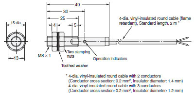
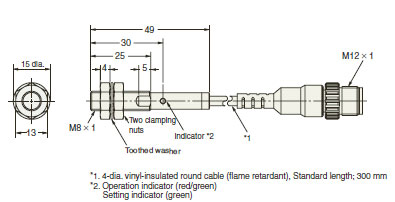
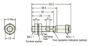
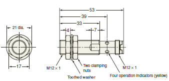
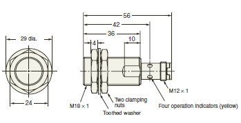
(Unit: mm)
Tolerance class IT16 applies to dimensions in this data sheet unless otherwise specified.


Reviews
There are no reviews yet.