
| Appearance | Sensing distance | Model | |
|---|---|---|---|
| Operation mode | |||
| NO | NC | ||
Unshielded |
5 mm | TL-W5MD1 2M *1 *2 | TL-W5MD2 2M *2 |

Liên hệ

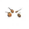
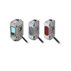
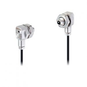
• Chỉ dày 6 mm nhưng cung cấp khoảng cách phát hiện 3 mm (TL-W3MC1).
• Các mẫu nhôm đúc cũng có sẵn.
| Appearance | Sensing distance | Model | |
|---|---|---|---|
| Operation mode | |||
| NO | NC | ||
| Unshielded |
5 mm | TL-W5MD1 2M *1 *2 | TL-W5MD2 2M *2 |
| Appearance | Sensing distance |
Output configuration |
Model | |
|---|---|---|---|---|
| Operation mode | ||||
| NO | NC | |||
| Unshielded |
1.5 mm | NPN | TL-W1R5MC1 2M *1 *2 | — |
| PNP | TL-W1R5MB1 2M | — | ||
| 3 mm | NPN | TL-W3MC1 2M *1 *2 | TL-W3MC2 2M *1 *2 | |
| PNP | TL-W3MB1 2M *2 | TL-W3MB2 2M *2 | ||
| 5 mm | NPN | TL-W5MC1 2M *1 *2 | TL-W5MC2 2M | |
| PNP | TL-W5MB1 2M | TL-W5MB2 2M | ||
| 20 mm | NPN | TL-W20ME1 2M *1 | TL-W20ME2 2M *1 | |
Shielded |
5 mm | NPN | TL-W5E1 2M | TL-W5E2 2M |
| PNP | TL-W5F1 2M | TL-W5F2 2M | ||
*1. Models with a different frequency are also available to prevent mutual interference.
The model numbers are TL-W[]M[][]5 (e.g., TL-W5MD15).
*2. Models are also available with robotics (bend resistant) cables. Add “-R” to the model number.
(e.g., TL-W5MC1-R 2M)
Order a Nut Set when required, e.g., if you lose the nuts.
| Model | Applicable Sensors | Quantity |
|---|---|---|
| Y92E-D2R5 | TL-W1R5[] | 1 |
| Model | TL-W5MD[] | |
|---|---|---|
| Sensing distance | 5 mm ±10% | |
| Set distance | 0 to 4 mm | |
| Differential travel | 10% max. of sensing distance | |
| Detectable object | Ferrous metal (The sensing distance decreases with non-ferrous metal. Refer to Engineering Data on Data Sheet.) |
|
| Standard sensing object | Iron, 18 × 18 × 1 mm | |
| Response frequency *1 | 500 Hz | |
| Power supply voltage (operating voltage range) |
12 to 24 VDC (10 to 30 VDC), ripple (p-p): 10% max. | |
| Leakage current | 0.8 mA max. | |
| Control output |
Load current | 3 to 100 mA |
| Residual voltage | 3.3 V max. (under load current of 100 mA with cable length of 2 m) | |
| Indicators | D1 Models: Operation indicator (red), Setting indicator (green) D2 Models: Operation indicator (red) |
|
| Operation mode (with sensing object approaching) |
D1 Models: NO D2 Models: NC Refer to the timing charts under I/O Circuit Diagrams on Data Sheet for details. |
|
| Protection circuits | Load short-circuit protection, Surge suppressor | |
| Ambient temperature range | Operating/Storage: -25 to 70°C (with no icing or condensation) | |
| Ambient humidity range | Operating/Storage: 35% to 95% (with no condensation) | |
| Temperature influence | ±10% max. of sensing distance at 23°C in the temperature range of -25 to 70°C | |
| Voltage influence | ±2.5% max. of sensing distance at rated voltage in the rated voltage ±15% range | |
| Insulation resistance | 50 MΩ min. (at 500 VDC) between current-carrying parts and case | |
| Dielectric strength | 1,000 VAC for 1 min between current-carrying parts and case | |
| Vibration resistance | Destruction: 10 to 55 Hz, 1.5-mm double amplitude for 2 hours each in X, Y, and Z directions | |
| Shock resistance | Destruction: 500 m/s2 3 times each in X, Y, and Z directions | |
| Degree of protection | IEC 60529 IP67, in-house standards: oil-resistant *2 | |
| Connection method | Pre-wired Models (Standard cable length: 2 m) | |
| Weight (packed state) | Approx. 80 g | |
| Materials | Case | Heat-resistant ABS |
| Sensing surface | ||
| Accessories | Instruction manual | |
| Model | TL-W1R5MC1 TL-W1R5MB1 |
TL-W3MC[] TL-W3MB[] | TL-W5MC[] TL-W5MB[] | TL-W5E1 TL-W5E2 TL-W5F1 TL-W5F2 |
TL-W20ME1 TL-W20ME2 |
|
|---|---|---|---|---|---|---|
| Sensing distance | 1.5 mm ±10% | 3 mm ±10% | 5 mm ±10% | 20 mm ±10% | ||
| Set distance | 0 to 1.2 mm | 0 to 2.4 mm | 0 to 4 mm | 0 to 16 mm | ||
| Differential travel | 10% max. of sensing distance | 1% to 15% of sensing distance | ||||
| Detectable object | Ferrous metal (The sensing distance decreases with non-ferrous metal. Refer to Engineering Data on Data Sheet.) |
|||||
| Standard sensing object | Iron, 8 × 8 × 1 mm |
Iron, 12 × 12 × 1 mm |
Iron, 18 × 18 × 1 mm |
Iron, 50 × 50 × 1 mm |
||
| Response frequency | 1 kHz min. | 600 Hz min. | 500 Hz min. | 300 Hz min. | 40 Hz min. | |
| Power supply voltage (operating voltage range) |
12 to 24 VDC (10 to 30 VDC), ripple (p-p): 10% max. | 12 to 24 VDC (10 to 30 VDC), ripple (p-p): 20% max. | 12 to 24 VDC (10 to 30 VDC), ripple (p-p): 10% max. | |||
| Current consumption | 15 mA max. at 24 VDC (no-load) | 10 mA max. at 24 VDC (no-load) |
15 mA max. at 24 VDC (no-load) |
8 mA at 12 VDC, 15 mA at 24 VDC |
||
| Control output |
Load current |
TL-W1R5MC1/-W3MC[]: NPN open collector 100 mA max. at 30 VDC max. TL-W1R5MB1/-W3MB[]: PNP open collector 100 mA max. at 30 VDC max. |
TL-W5MC[]: NPN open collector 50 mA max. at 12 VDC (30 VDC max.) 100 mA max. at 24 VDC (30 VDC max.) TL-W5MB[]: PNP open collector 50 mA max. at 12 VDC (30 VDC max.) 100 mA max. at 24 VDC (30 VDC max.) |
200 mA | 100 mA max. at 12 VDC 200 mA max. at 24 VDC |
|
| Residual voltage |
1 V max. (under load current of 100 mA with cable length of 2 m) | 2 V max. (under load current of 200 mA with cable length of 2 m) | 1 V max. (under load current of 200 mA with cable length of 2 m) | |||
| Indicators | Detection indicator (red) | |||||
| Operation mode (with sensing object approaching) |
NO | B1/C1 Models: NO B2/C2 Models: NC |
E1/F1 Models: NO E2/F2 Models: NC |
|||
| Refer to the timing charts under I/O Circuit Diagrams on Data Sheet for details. | ||||||
| Protection circuits | Reverse polarity protection, Surge suppressor | |||||
| Ambient temperature range |
Operating/Storage: -25 to 70°C (with no icing or condensation) * | |||||
| Ambient humidity range | Operating/Storage: 35% to 95% (with no condensation) | |||||
| Temperature influence | ±10% max. of sensing distance at 23°C in the temperature range of -25 to 70°C | |||||
| Voltage influence | ±2.5% max. of sensing distance at rated voltage in the rated voltage ±10% range | ±2.5% max. of sensing distance at rated voltage in the rated voltage ±20% range | ±2.5% max. of sensing distance at rated voltage in the rated voltage ±10% range | |||
| Insulation resistance | 50 MΩ min. (at 500 VDC) between current-carrying parts and case | |||||
| Dielectric strength | 1,000 VAC, 50/60 Hz for 1 minute between current-carrying parts and case | |||||
| Vibration resistance | Destruction: 10 to 55 Hz, 1.5-mm double amplitude for 2 hours each in X, Y, and Z directions | |||||
| Shock resistance | Destruction: 500 m/s2 3 times each in X, Y, and Z directions | Destruction: 500 m/s2 10 times each in X, Y, and Z directions | ||||
| Degree of protection | IEC 60529 IP67, in-house standards: oil-resistant * | |||||
| Connection method | Pre-wired Models (Standard cable length: 2 m) | |||||
| Weight (packed state) | Approx. 70 g | Approx. 80 g | Approx. 100 g | Approx. 210 g | ||
| Materials | Case | Heat-resistant ABS | Aluminum die-cast | Heat-resistant ABS | ||
| Sensing surface |
Heat-resistant ABS | |||||
| Accessories | Mounting Bracket, Instruction manual |
Instruction manual | ||||
* For environments that require oil resistance, the upper limit of the ambient operating temperature range is 40°C.
(Unit: mm)
Tolerance class IT16 applies to dimensions in this data sheet unless otherwise specified.
TL-W1R5MB1
TL-W1R5MC1
TL-W3MB[] TL-W3MC[]
TL-W5MB[] TL-W5MC[] TL-W5MD[]
TL-W5E[] TL-W5F[]


Reviews
There are no reviews yet.