The model numbers used to order sets are illustrated below. One set comprises the Operation Unit, Lamp, and Socket Unit. For more information, refer to Ordering Information. Some forms may not be available for order depending on the combination of functions and specifications described below. Contact your OMRON sales representative for more detailed information.
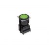
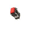
Nút nhấn có đèn Omron A3S
Liên hệ
Liên Hệ Tư Vấn
Sê-ri công tắc nút nhấn có thân hình vuông 40 mm
• Kết hợp thiết kế thu nhỏ với cảm giác vận hành khác biệt nhưng nhẹ nhàng.
• Dễ dàng gắn bảng điều khiển từ phía trước và thay thế đèn đơn giản mà không cần dụng cụ.
Đặc điểm
Model Number Legend
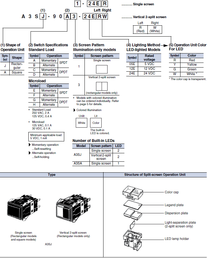
Ordering Information
Ordering as a Set
The model numbers used to order sets of Units are given in the following tables. One set comprises the Operation Unit, Lamp, and Socket Unit. Not all combinations are possible. Ask your OMRON representative for details.
Standard Loads

Single screen
| Contact type | Standard load (250 VAC, 2 A; 125 VDC 0.4 A) | Operation Unit color symbol | |||
|---|---|---|---|---|---|
| Operation | Momentary operation (Self-resetting) |
Alternate operation (Self-holding) |
|||
| Output | Lighting | ||||
| SPDT | LED | 5 VDC | A3SJ-90A1-05E[] | A3SJ-90B1-05E[] | Enter the desired color symbol for the Pushbutton in []. R (Red) Y (Yellow) G (Green) W (White) |
| 12 VDC | A3SJ-90A1-12E[] | A3SJ-90B1-12E[] | |||
| 24 VDC | A3SJ-90A1-24E[] | A3SJ-90B1-24E[] | |||
| DPDT | LED | 5 VDC | A3SJ-90C1-05E[] | A3SJ-90D1-05E[] | |
| 12 VDC | A3SJ-90C1-12E[] | A3SJ-90D1-12E[] | |||
| 24 VDC | A3SJ-90C1-24E[] | A3SJ-90D1-24E[] | |||
Vertical 2-split screen
| Contact type | Standard load (250 VAC, 2 A; 125 VDC 0.4 A) | Operation Unit color symbol | |||
|---|---|---|---|---|---|
| Operation | Momentary operation (Self-resetting) |
Alternate operation (Self-holding) |
|||
| Output | Lighting | ||||
| SPDT | LED | 24 VDC | A3SJ-90A3-24E[][] | A3SJ-90B3-24E[][] | Enter the desired color symbol for the Pushbutton in [][]. R (Red) Y (Yellow) G (Green) W (White) |
| DPDT | LED | 24 VDC | A3SJ-90C3-24E[][] | A3SJ-90D3-24E[][] | |
Microloads
Single screen
| Contact type | Microload (125 VAC, 0.1 A; 30 VDC 0.1 A) |
Operation Unit color symbol | ||
|---|---|---|---|---|
| Operation | Momentary operation (Self-resetting) |
|||
| Output | Lighting | |||
| SPDT | LED | 12 VDC | A3SJ-90E1-12E[] | Enter the desired color symbol for the Pushbutton in []. R (Red) Y (Yellow) G (Green) W (White) |
| 24 VDC | A3SJ-90E1-24E[] | |||
| DPDT | LED | 5 VDC | A3SJ-90G1-05E[] | |
| 12 VDC | A3SJ-90G1-12E[] | |||
| 24 VDC | A3SJ-90G1-24E[] | |||
Vertical 2-split screen
| Contact type | Microload (125 VAC, 0.1 A; 30 VDC 0.1 A) |
Operation Unit color symbol | ||
|---|---|---|---|---|
| Operation | Momentary operation (Self-resetting) |
|||
| Output | Lighting | |||
| SPDT | LED | 24 VDC | A3SJ-90E3-24E[][] | Enter the desired color symbol for the Pushbutton in [][]. R (Red) Y (Yellow) G (Green) W (White) |
| DPDT | LED | 24 VDC | A3SJ-90G3-24E[][] | |
Standard Loads

Single screen
| Contact type | Standard load (250 VAC, 2 A; 125 VDC 0.4 A) | Operation Unit color symbol |
|||
|---|---|---|---|---|---|
| Operation | Momentary operation (Self-resetting) |
Alternate operation (Self-holding) |
|||
| Output | Lighting | ||||
| SPDT | LED | 5 VDC | A3SA-90A1-05E[] | A3SA-90B1-05E[] | Enter the desired color symbol for the Pushbutton in []. R (Red) Y (Yellow) G (Green) W (White) |
| 12 VDC | A3SA-90A1-12E[] | A3SA-90B1-12E[] | |||
| 24 VDC | A3SA-90A1-24E[] | A3SA-90B1-24E[] | |||
| DPDT | LED | 5 VDC | A3SA-90C1-05E[] | A3SA-90D1-05E[] | |
| 12 VDC | A3SA-90C1-12E[] | A3SA-90D1-12E[] | |||
| 24 VDC | A3SA-90C1-24E[] | A3SA-90D1-24E[] | |||
Microloads
Single screen
| Contact type | Microload (125 VAC, 0.1 A; 30 VDC 0.1 A) |
Operation Unit color symbol | ||
|---|---|---|---|---|
| Operation | Momentary operation (Self-resetting) |
|||
| Output | Lighting | |||
| SPDT | LED | 5 VDC | A3SA-90E1-05E[] | Enter the desired color symbol for the Pushbutton in []. R (Red) Y (Yellow) G (Green) W (White) |
| 12 VDC | A3SA-90E1-12E[] | |||
| 24 VDC | A3SA-90E1-24E[] | |||
| DPDT | LED | 5 VDC | A3SA-90G1-05E[] | |
| 12 VDC | A3SA-90G1-12E[] | |||
| 24 VDC | A3SA-90G1-24E[] | |||
Ordering Individually
Operation Units, Lamps, and Socket Units can be ordered separately. Combinations that are not available as sets can be created using individual Units. Also, store the parts as spares for maintenance and repairs.
Operation Unit
LED-lighted Models (LED is not built in.)
| Appearance | Rectangular Models (2 LEDs) (transparent legend plate |
Square Models (1 LED) (transparent legend plate |
|||
|---|---|---|---|---|---|
| Screen pattern | Display color | ||||
| Single screen |  |
White | A3SJ-5801 | A3SA-5801 | |
| Red | A3SJ-5802 | A3SA-5802 | |||
| Green | A3SJ-5803 | A3SA-5803 | |||
| Yellow | A3SJ-5805 | A3SA-5805 | |||
| 2-split screen * |
Standard split screen |
 |
White/red | A3SJ-5901 | — |
| White/green | A3SJ-5902 | ||||
| White/yellow | A3SJ-5904 | ||||
| Red/green | A3SJ-5905 | ||||
| Red/yellow | A3SJ-5907 | ||||
| Green/yellow | A3SJ-5909 | ||||
| Reverse split screen |
Red/white | A3SJ-5911 | — | ||
| Green/white | A3SJ-5912 | ||||
| Green/red | A3SJ-5915 | ||||
| Yellow/red | A3SJ-5917 | ||||
| Yellow/green | A3SJ-5919 | ||||
| One-color 2-split screen |
White/white | A3SJ-5921 | — | ||
| Red/red | A3SJ-5922 | ||||
| Green/green | A3SJ-5923 | ||||
| Yellow/yellow | A3SJ-5925 | ||||
Note: The color cap is transparent when the display color is white.
* Two-split screen configurations are given with the OMRON surface of the case downward.
Lamp
LED Lamp
| Operating voltage | 5 VDC | 12 VDC | 24 VDC |
|---|---|---|---|
| Color | Model (DC only) | Model (DC only) | Model (DC only) |
| Red | SLL-05ER | SLL-12ER | SLL-24ER |
| Yellow | SLL-05EY | SLL-12EY | SLL-24EY |
| Green | SLL-05EG | SLL-12EG | SLL-24EG |
| White | SLL-05EW | SLL-12EW | SLL-24EW |
Note: The A3SJ (M2SJ) requires two LEDs for each Switch. The A3SA (M2SA) requires one LED.
Switch (LED models)
| Appearance | Rectangular models  |
Square models  |
Selection precautions | |||
|---|---|---|---|---|---|---|
| Contact type | Number of outputs |
Operation | ||||
| Standard load |
Silver contacts |
1 | Momentary operation | A3SJ-8010 | A3SA-7010 | Use the Socket Unit in combination with the same shape Operation Unit (rectangular or square). Example: For the A3SJ-5801 Rectangular Operation Unit, select the A3SJ-8[][]0 Socket Unit. Momentary operation is self-resetting, |
| Alternate operation | A3SJ-8020 | A3SA-7020 | ||||
| 2 | Momentary operation | A3SJ-8030 | A3SA-7030 | |||
| Alternate operation | A3SJ-8040 | A3SA-7040 | ||||
| Microload | Gold alloy contacts |
1 | Momentary operation | A3SJ-8050 | A3SA-7050 | |
| Alternate operation | A3SJ-8060 | A3SA-7060 | ||||
| 2 | Momentary operation | A3SJ-8070 | A3SA-7070 | |||
| Alternate operation | A3SJ-8080 | A3SA-7080 | ||||
Accessories, Replacements, and Tools
Accessories for Rectangular Models
| Name | Appearance | Classification | Model | Application precautions |
|---|---|---|---|---|
| Barrier |
 |
Short edge Barriers (1 pair) | A3SA-4001 | The purpose of a Barrier is to prevent malfunctioning and to improve design image of the mounting panel. There is one intermediate Barrier and one pair of edge Barriers (2 Barriers). Mount Short Barriers horizontally. Mount Long Barriers vertically. |
| Short intermediate Barriers | A3SA-4002 | |||
| Long edge Barriers (1 pair) | A3SJ-4003 | |||
| Long intermediate Barriers | A3SJ-4004 | |||
| Switch Guard |
 |
– | A3SJ-5050 | Cannot be used with Barrier or Seal Cover. |
| Seal Cover |
 |
– | A3SJ-5060 | Cannot be used with Barrier or Switch Guard. Cap material: Vinyl chloride |
| Long Mounting Plate |
 |
1 pair | A3SJ-3002 | Use when vertically mounting individual (with Barrier) or multiple Switches (in standard mounting style and with Barrier). A Short Mounting Plate is attached to the Switch; replace it with the long one. |
Accessories for Square Models
| Name | Appearance | Classification | Model | Application precautions |
|---|---|---|---|---|
| Barrier |
 |
Short Edge Barriers (1 pair) | A3SA-4001 | The purpose of the Barrier is to prevent malfunctioning and to improve design image of the mounting panel. |
| Short Intermediate Barrier | A3SA-4002 | |||
| Switch Guard |
 |
– | A3SA-5050 | Cannot be used with Barrier or Seal Cover. |
| Seal Cover |
 |
– | A3SA-5060 | Cannot be used with Barrier or Switch Guard. Cap material: Vinyl chloride |
Replacements for Rectangular Models
| Name | Appearance | Classification | Model | Application precautions | |
|---|---|---|---|---|---|
| Socket |  |
Wire-wrap terminals | A3SJ-4104 | Sockets cannot be used for multiple mounting. |
|
| PCB terminals | A3SJ-4105 | ||||
| Solder terminals | A3SJ-4106 | ||||
| Dispersion plate |
 |
Milk-white | Single screen |
A3SJ-5107 | – |
| Color cap |  |
Transparent | Single screen |
A3SJ-5600 | • Contact your OMRON representative for color changes or inscribing. • If LEDs are to be used, use a color cap that matches the LED color. |
| White | A3SJ-5601 | ||||
| Red | A3SJ-5602 | ||||
| Green | A3SJ-5603 | ||||
| Yellow | A3SJ-5605 | ||||
 |
Transparent | 2-split screen |
A3SJ-5630 | ||
| Green | A3SJ-5633 | ||||
| Yellow | A3SJ-5635 | ||||
| Legend plate |
 |
Transparent | A3SJ-4204 | A transparent legend plate is mounted on the Operation Unit. |
|
| Milk-white | A3SJ-4203 | ||||
Replacements for Square Models
| Name | Appearance | Classification | Model | Application precautions |
|---|---|---|---|---|
| Socket |  |
Wire-wrap terminals | A3SA-4101 | Sockets cannot be used for multiple mounting. |
| PCB terminals | A3SA-4102 | |||
| Solder terminals | A3SA-4103 | |||
| Dispersion plate |
 |
Milk-white | A3SA-5107 | – |
| Color cap |  |
Transparent | A3SA-5600 | • Contact your OMRON representative for color changes or inscribing. • If LED colors are to be used, use a color cap that matches the LED color. |
| White | A3SA-5601 | |||
| Red | A3SA-5602 | |||
| Green | A3SA-5603 | |||
| Blue | A3SA-5604 | |||
| Yellow | A3SA-5605 | |||
| Legend plate |
 |
Transparent | A3SA-4204 | A transparent color cap is mounted to a standard Display. |
| Milk-white | A3SA-4203 |
Tools
| Name | Appearance | Classification | Model | Application precautions |
|---|---|---|---|---|
| Extractor |
 |
– | A3PJ-5080 | Convenient for extracting the Operation Unit. |
Thông số kỹ thuật
Approved Standard Ratings
UL (File No. E41515), CSA (File No. LR45258)
2 A at 250 VAC
Microload: 0.1 A at 125 VAC
0.1 A at 30 VDC
Note: Certification has been obtained for the Switch Unit.
For detailed information on individual products that have received certification, consult your supplier.
Ratings
For Standard Loads
| Rated voltage | Non-inductive load (A) | Inductive load (A) | ||||||
|---|---|---|---|---|---|---|---|---|
| Resistive load | Lamp load | Inductive load | Motor load | |||||
| NC | NO | NC | NO | NC | NO | NC | NO | |
| 125 VAC 250 VAC |
3 2 |
1 0.7 |
0.7 0.5 |
2 1.5 |
1.5 1 |
1 0.7 |
||
| 8 VDC 14 VDC 30 VDC 125 VDC 250 VDC |
3 3 2 0.4 0.2 |
1 1 1 0.05 0.03 |
2 1.5 1.5 0.4 0.2 |
1.5 1.5 1 0.05 0.03 |
||||
2. Inductive load: Power factor = 0.4; time constant = 7 ms.
3. The lamp load has an inrush current of 10 times the steady-state current.
4. The motor load has an inrush current of 6 times the steady-state current.
The rated values are for testing conducted under the following conditions.
(1) Ambient temperature: 20±2°C
(2) Ambient humidity: 65% ±5%RH
(3) Operating frequency: 20 times/min
For Microloads
| Rating | 0.1 A at 30 VDC (resistive load); 0.1 A at 125 VAC (resistive load) |
|---|---|
| Minimum applicable load | 1 mA at 5 VDC |
LED Lamp
| Type | Applied voltage | Rated voltage | Rated current | Built-in limiting resistance |
|---|---|---|---|---|
| DC only | 5 VDC ± 5% | 5 VDC | 30 mA | 39 Ω |
| 12 VDC ± 5% | 12 VDC | 15 mA | 270 Ω | |
| 24 VDC ± 5% | 24 VDC | 12.5 mA | 1300 Ω |
Characteristics
| Operating frequency | Mechanical | Momentary operation models: 120 operations/min max. *1 |
|---|---|---|
| Electrical | 20 operations/min max. | |
| Insulation resistance | 100 MΩ min. (at 500 VDC) | |
| Contact resistance | Standard load | 50 mΩ max. (initial value) |
| Microload | 50 mΩ max. (initial value) | |
| Dielectric strength | Between terminals of same polarity | 1,000 VAC, 50/60 Hz for 1 minute |
| Between terminals of different polarity | 2,000 VAC, 50/60 Hz for 1 minute | |
| Between current-carrying metal part and ground |
2,000 VAC, 50/60 Hz for 1 minute | |
| Between each terminal and non- current-carrying metal part |
2,000 VAC, 50/60 Hz for 1 minute | |
| Between lamp terminals | 1,000 VAC, 50/60 Hz for 1 minute *2 | |
| Vibration resistance | Malfunction | 10 to 55 Hz, 1.5-mm double amplitude *3 |
| Shock resistance | Destruction | 500 m/s2 max. |
| Malfunction | 200 m/s2 max. *3 | |
| Life expectancy | Mechanical | Momentary operation models: 1,000,000 operations min. Alternate operation models: 100,000 operations min. (One operation consists of set and reset operations.) |
| Electrical | 100,000 operations min. (rated load) | |
| Weight | Approx. 10 g | |
| Inrush current | NC | Standard load: 10 A max. |
| NO | Standard load: 10 A max. | |
| Ambient operating temperature | – 10 to 50 °C (with no icing or condensation) | |
| Ambient operating humidity | 35% to 85% RH | |
| Ambient storage temperature | – 25 to 65 °C (with no icing or condensation) | |
| Degree of protection | IP00 | |
| Electric shock protection class | Class II | |
| PTI (proof tracking index) | 175 | |
| Pollution degree | 3 (IEC 60947-5-1) | |
*1. With alternate operation models, 60 operations/min max. One operation cycle consists of set and reset operations.
*2. With no LED lamp mounted.
*3. Malfunction : 1 ms max.
Operating Characteristics
| Operation | Momentary operation models | Alternate operation models | |
|---|---|---|---|
| Operating characteristics | |||
| Operating force | OF max. | 3.92 N | 4.90 N |
| Releasing force | RF min. | 0.49 N | 0.294 N |
| Total travel | TT | Approx. 3 mm | Approx. 3 mm |
| Pretravel | PT max. | 2.2 mm | 2.2 mm |
| Lock travel alternate | LTA min. | – | 0.5 mm |
Contact Form
| Name | Contact Form |
|---|---|
| Double-throw contacts |
 |
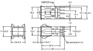
Kích thước
(Unit: mm)
The Dimension shows 2-switch outputs.
Rectangular Models (A3SJ)
Square Models (A3SA)
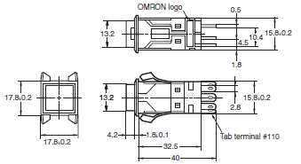
Note: Unless specified, a tolerance of ±0.4 mm applies for all dimensions. Use a mounting panel thickness of 1 to 4 mm.
Accessory Mounting Dimensions
Legend Plate
Rectangular Models
A3SJ-4203/-4204

Square Models
A3SA-4203/-4204

Extractor
A3PJ-5080
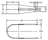
Note: Made from stainless steel.
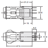
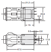
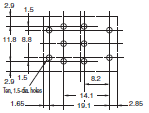
Socket-mounting Dimensions
Rectangular Models
Wire-wrap Terminals
A3SJ-4104
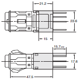
Solder Terminals
A3SJ-4106
PCB Terminals
A3SJ-4105
Terminal Hole Dimensions

PCB Cutout (Bottom View)
Square Models
Wire-wrap Terminals
A3SA-4101
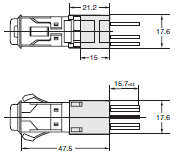
Solder Terminals
A3SA-4103
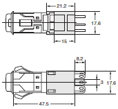
PCB Terminals
A3SA-4102
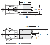
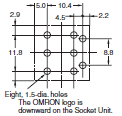
Terminal Hole Dimensions

PCB Cutout (Bottom view)
Switch and Guard Mounting Dimensions
Rectangular Models
A3SJ-5050
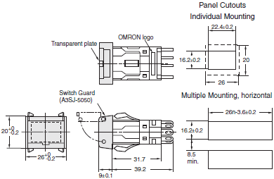
Square Models
A3SA-5050
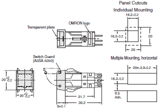
Seal Cover Mounting Dimensions
Rectangular Models
A3SJ-5060
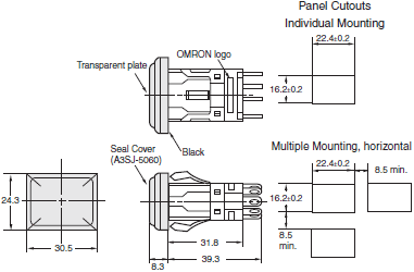
Square Models
A3SA-5060
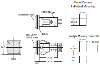
2. Unless otherwise specified, a tolerance of ±0.4 mm applies to all dimensions.
MODEL
| STT | Chi tiết | Tiêu đề | Tải xuống |
| 1 | DANH SÁCH MODEL | A3S | Item list of A3S |




Reviews
There are no reviews yet.