

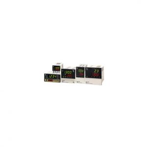
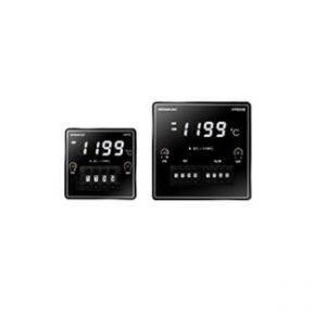
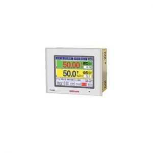
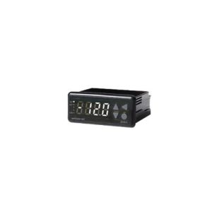
Bộ điều khiển nhiệt độ Hanyoung TD300-11
Liên hệ

Liên hệ :
08 88 44 88 99
Liên hệ :
0978 63 73 78
Liên hệ :
0909 63 73 78
Liên Hệ Tư Vấn
Lưu ý: Quý khách có thể tùy chọn mẫu sản phẩm hoặc liên hệ để được tư vấn
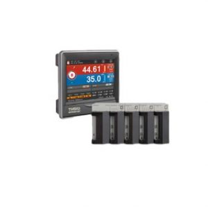
TD300 Programmable Temperature Controller
– Màn hình LCD màu với bảng điều khiển cảm ứng
– Điều khiển 2 kênh
– Lên tới 100 mẫu, 100 phân đoạn/mẫu (tổng cộng 2.400 phân đoạn)
– Điều khiển PID
– Chức năng cảnh báo đa dạng (đầu ra: 4 tiếp điểm, hoạt động: 20 loại)
– 8 tiếp điểm ngõ vào số (DI), 8 tiếp điểm ngõ ra số (DO)
– Chức năng giao tiếp (RS485 hoặc RS232, tùy thuộc vào mã hậu tố)
– Lưu trữ dữ liệu và sao lưu thông số qua thẻ SD
· Suffix code
| MODEL | CODE | DESCRIPTION | |
| TD300- | 2 CHANNLE PROGRAMMABLE TEMPERATURE CONTROLLER 96(W)×96(H)×100(D) | ||
| Communication | 1 | RS485/422 | |
| 2 | RS232C | ||
| language | 1 | Korean / English (Standard) | |
| 2 | English / Chinese (Simplified) | ||
· Specification
| [ Input Specification ] |
| Input (2 channels) |
Pt100 (IEC751) |
-200.0 ~ 640.0 ℃, ± 0.1 % of F.S |
| TC_K | -200.0 ~ 1370.0 ℃, ± 0.1 % of F.S | |
| TC_J | -200.0 ~ 1200.0 ℃, ± 0.1 % of F.S | |
| TC_E | -200.0 ~ 1000.0 ℃, ± 0.1 % of F.S | |
| TC_T | -200.0 ~ 400.0 ℃, ± 0.1 % of F.S | |
| TC_R | 0 ~ 1700.0 ℃, ± 0.1 % of F.S | |
| TC_S | 0 ~ 1700.0 ℃, ± 0.1 % of F.S | |
| mV | 0 ~ 100 mV or -10 ~ 20 mV (-999.9 ~ 9999.9), ± 0.1 % of F.S | |
| V DC | 0 – 10 V (Signal Input Range setup is available, -999.9 ~ 9999.9), ±0.1 % of FS | |
| 4 – 20 mA | Use 250 Ω external resistance, V DC Use after setup of V DC 1 – 5 V | |
| Input Resolution | 24 bit | |
| Accuracy of indication | 0.1 % | |
| Sampling cycle | 500 msec | |
| Input Resistance | More than 1 ㏁ | |
| Maximum allowable resistance of line | Less than 50 Ω / Line (Resistance of lines is a same condition) | |
| RJC | ±1.5 ℃ | |
| [ Output Specification ] |
| Control Output (2 channels) |
SCR | 4 – 20 mA DC(Resistive load : less than 600 Ω) Output Resolution : 16 bit Accuracy of Output : ±0.1 % of FS Output Ripple : 0.2 % of FS |
| SSR | 24 V DC Pulse (Resistive load : More than 600Ω) Min. Pulse Range : 10 ms Cycle Time : Available to select 1 – 1000 s |
|
| Relay Output | Kind of Internal Relay : N/O -> 250 V AC 5 A / 30 V DC 5 A | |
| Transmission Output (4 – 20 mA) |
Avaliable to select PV/SV/H.MV/C.MV of each channel Output Accuracy : ±0.1 % of FS In case of heating/cooling control, if control output of heating is SCR or SSR, this channel can not use transmission output. |
|
| Transmission Output Period of outputrenewal | Each channel 500 ms | |
| [ Functions ] |
| Screen | 3.5” TFT-LCD |
| Pattern | Max 100 , Available to operate each channel’s pattern |
| Segment | Max 2,400 ( Max 100 per segment) |
| Waiting Mode | Setup per pattern and setup of using or not using per segment |
| Repetition & Connection | Available to use Pattern Repetition and Section Repeat Loof Setup (Max. 20) Free connecting operation among patterns is available |
| PID Group | Each channel 4 Zones, Selectable between manual or automatic |
| Control Method | Heating control or Heating/Cooling control in each channel. PID or ON/OFF control |
| Auto Tuning | Optimal PID GAIN is automatically calculated according to Set Value. It could be operated by each channel |
| Proportional Band | 0.0 ~ 1000.0 ℃ ( If “0” = On/Off control, Not “0” = PID control) |
| Integral Time | 0 ~ 6000 sec ( “0” = No Integral Calculation) |
| Differential Time | 0 ~ 6000 sec ( “0” = No Differential Calculation) |
| ON/OFF control | Available to select Dead zone 0.1 ~ 1000.0 ℃ |
| Event Log | Max 40 Event Logs could be saved depend on various situations |
| LCD protection | Back light will be off according to designated time of not using touch panel |
| Password | Password is available to prevent other people from changing system setup |
| Protection of Over-Integral and Differential | ARW Zone setup ( 50 ~ 200 % of proportional band) |
| Fuzzy Function | Control overshoot |
| RAMP | Available to select SV changing ratio in case of fixing operation |
| Restrict MV changing ratio |
Function to control sudden change of MV |
| Alarm Setup | 4 points, High, Low, Deviation etc. 20 kinds |
| Inner Signal | 8 points, object, range and delayed time setup are available |
| Time Signal | 8 points when program mode operation |
| Graph Function | PV, SV of each channel could be display by graph |
| Fixing Operation Hour | Available to set fixing operation hour up |
| Reservation Operation Fuction |
Available to use reservation operation time by using built in timer. |
| User Logo Display | User logo could be shown for 3 sec after power on. Download through communication port |
| Screen Capture | Upload is available through communication port |
| Language | Korean and English (Or Chinese / English optional) |
| Contact Input | RUN/STOP, STEP, HOLD and Error Input (Stop operation, Delayed/ setup is available) |
| Contact Output | Output of various signals |
| Storage in Power Failure | Various setting and operation information memory |
| Blackout return | STOP / COLD / HOT return when power failure is restored |
| [ Communication ] |
| Applied Standard | EIA-RS232C, EIA-RS422/485, USB | |
| Max.Connection Number | RS232 | 1 : 1 |
| RS422 / 485 | 1 : 256 | |
| Communication Method | RS232 | Full Duplex |
| RS422 / 485 | 4 wired Half Duple, 2 wired Half Duplex | |
| Synchronous Method | RS232 RS422 / 485 |
asynchronous |
| Communication Distance | RS232 | Within approximately 10 m |
| RS422 / 485 | Within approximately 1.2 Km | |
| Communication Speed | RS232 RS422 / 485 |
2400 ~ 115200 bps |
| Length of Data | RS232 RS422 / 485 |
PCLINK : 8 bit / Modbus-ASCII : 7 bit |
| Parity Bit | RS232 RS422 / 485 |
PCLINK : NONE / Modbus-ASCII : EVEN |
| Stop Bit | RS232 RS422 / 485 |
1 bit |
| Communication Protocol | RS232 RS422 / 485 |
PCLINK, Modbus-ASCII |
| Delayed Response Time | RS232 RS422/485 |
1 + (0 ~ 250) ㎳ |
| [ Ratings ] |
| Rated Voltage | 100 – 240 V AC, Valiable Voltage Ratio : ±10 % | |
| Frequecy | 50 – 60 Hz | |
| Power Consumption | Max. 10 W | |
| Insulation resistance | Between 1st & 2nd Terminal 1st/2nd and Earth Terminal |
More than 20 ㏁ /500 V DC |
| Dielectric strength | Between 1st & 2nd Terminal 1st/2nd and Earth Terminal |
2500 V ac, 50 / 60 Hz, 1 분간 |
| Power output | 24 V d.c, 1A Max. (TD500 only) | |
| [Operation Environment] |
| Installation | Continuous Vibration | Vibration Wide : Bleow 1.2 mm (5 – 14 Hz) Below 4.9 ㎧ (4 – 150 Hz) |
| Short time Vibration | Below 14.7 ㎧ 15 sec(Each 3 directions) | |
| Shock | Below 147 ㎧ 11 msec (Each 6 directions, 3 times) |
|
| Normal Operation Condition |
Surrounding Temperature | 0 ~ 50 ℃ |
| Surrounding Humidity | 20 ~ 90 % RH (No Condensation) | |
| Magnetic Effect | Less than 400 AT/m | |
| Preheating | More than 10 minute | |
| Effectof surrounding temperature |
Voltage/TC Input | ± 1 uV / ℃ or ± 0.01 % of F.S / ℃ |
| RTD Input | Less than ±0.05 ℃ / ℃ | |
| Analog Output | Less than ±0.05 % of FS / ℃ |
| [Condition of Transport and Storage] |
| Temperature | -25 ~ 70 ℃ |
| Humidity | 5 ~ 95 % RH (No condensation) |
| Shock | Less than 1 m when dropping the packed product |
HƯỚNG DẪN SỬ DỤNG / MANUAL
| STT | Chi tiết | Tiêu đề | Tải xuống |
| 1 | Hướng dẫn sử dụng | TD300 manual |
TÀI LIỆU / BROCHURE
| STT | Chi tiết | Tiêu đề | Tải xuống |
| 1 | Tài liệu | Total Product Guide 2018 ver. |
CAD
| STT | Chi tiết | Tiêu đề | Tải xuống | |
| 1 | CAD |
|
||
| 2 | CAD | TD300 |
Communication
| STT | Chi tiết | Tiêu đề |
| 1 | PROGRAM | Integrated Communication Program (TCS) |
Be the first to review “Bộ điều khiển nhiệt độ Hanyoung TD300-11”
SẢN PHẨM LIÊN QUAN
Liên hệ

Reviews
There are no reviews yet.